
What follows are my notes from a demonstration given at the Maker_Space 3D Thursday of Jason Spiller’s David Scan 3D scanning set-up.
The scanning process uses a digital camera and a projector. The projects projects light patterns onto the scene being scanned and the digital camera to capture the scene. The object being scanned is typically placed on a turntable so that all sides can be presented to the camera/projector set up. As the model is rotated on the turn table, images are collected by the camera from which the David Scan software generates 3d information about the scene.
The system demonstrated was a single camera set-up and was bought as a complete kit (calibration plate, camera, projector, software, turntable). The aproximate cost of the set-up was £4000, definitely positioning it towards the ‘pro’ end of the market.
The camera and the protector are mounted securely onto an aluminium beam (the red beam in the photographs). This creates a fixed relationship between the camera and the projector. It is important that this doesn’t change during the scanning process. The beam can then be mounted onto a tripod for ease of handling. The camera and projector are connected to a computer (Jason used a powerful laptop).
The calibration plates are used to calibrate the camera and projector pairing at the beginning of each scan. The two glass plates are (painted) white and have a grids of black dots. They are held at 90 degrees to each other with a bracket. Different sized dot grids are present in order that the camera set up can be calibrated for different sized objects/scenes (between 60 to 500 mm). Once calibrated, a resolution of up to 0.05% of scan size (up to .05 mm) can be achieved.
During calibration, the projector projects a series of black and white patterns onto the calibration plate. The camera captures the resulting scene and the David Scan software calculates the relationship between the camera and projector. Once calibrated, so long as the relationship between the camera and projector dosn’t not change, they can be moved around and will scan any scene they are pointed at.
In order to simplify the scanning process, a scan of the ‘background’ (minus the object to be scanned, but including the turntable) can be taken which can be subtracted from every subsequent scan so long as the camera/projector are not moved. Hence the use of a tripod. This is analogous with the way cameras on laptops can remove the background and superimpose a different background during video chat sessions so long as they are held static.
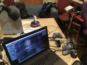
Image showing the calibration plate (top left), turntable (top centre), camera/projector set up (top right), and laptop running the David Scan software (foreground).
Jason set a small object (a Frankenstein’s monster toy) on the turntable and set the system up to take around 20 scans (18 degrees of rotation each time). The scanning process only took a few minutes. Each scan involves the projector projecting a series of black and while patterns (the structured light) onto the model followed by red, green, and blue in order to collect colour channel information. Because a background reference scan (sans model) had been taken, that was able to be subtracted from each scan. Hence only information that is different from the first ‘background’ scan is kept. The David scan software does a pretty good job of aligning the scanned geometry, but a degree of post processing is typically required.
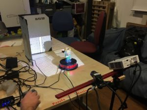
Here the structured light projection can be seen. The calibration plates are just behind the model, but once used for the ignition camera/projector calibration, they are not needed again.
Upon inspection, it was found that the scan had some information missing, so Jason ran another scan of the missing area with the camera/projector lowered to a different angle. Again this data was aligned, and stitched together with the first lot of scanned data. The resulting scan was very impressive (see below).
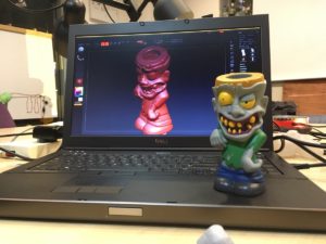
Image showing the original object and the 3d geometry created using the David Scan equipment/software. The software doesn’t show it, but the colour information collected was also very accurate.
Other things learnt from the demo:
- Not all object scan well. The equipment has difficulty resolving objects or features that are very shiny or very dull (matt black). In some instances, this can be overcome by spraying the object prior to scanning. The SKD-S2 substance can be used (although it is expensive), but there are also cheaper alternatives. I can’t remember what these were so if anyone else can (or Jason?), please amend/add here.
- Once the mesh model has been generated, it can be imported into Instant Mesh, a free ‘re-meshing’ program that allows to to add directionality to ‘quad’ mesh models.
- Jason offers a scanning and modelling service (google: Jason Spiller modelling).
Hope this was useful, any questions contact Jason or myself.