
Ever wanted to make an ‘Arduino’ on a bread board? Struggling to use an Arduino as an ISP programmer? (in spite of all the tutorials I was – some rare troubleshooting tips below!) Wished you could specify custom fuse settings, but finding it too much effort to work out where the setting is?
Read on to find out how I did all this and more…
I thought I’d write up what I had to do to get the Arduino ISP sketch working nicely*, and while I’m at it, I decided to explain what to do to use the Internal Oscillator at 8Mhz or 1Mhz (necessary for running the chip at < ~2.5V – to get the most out of two AA batteries).
*for my assessment of ‘nice’.
1. Programmers, Bootloaders and Boards
The Arduino environment has 3 concepts worth keeping in mind:
- the ‘programmer’ (physical device) you are going to use to program the chip,
- the board your chip is on,
- the bootloader that may need to be on the chip already for normal operation
The selected programmer defines the protocol that will be used to communicate with the device that is programming the chip. The chips can act as its own programmer (self-program) with a standard protocol if it already has the bootloader on it. If it doesn’t have the bootloader on it you have to use ISP (or ICSP as some may prefer) to program the chips through some extra external hardware (the programmer). Most of the time with Arduino boards the bootloader is used to self-program the chip, so no external programmer is required.
You have to use ISP to put the bootloader on, or change fuse settings.
The board is a more familiar concept – which physical board are you using? Mega2560, Leonardo, Mini Pro… there is a long list! This controls the fuse settings that must be programmed to make the device work. That’s because if the board doesn’t have an external crystal it will fail if the power on clock selected by the fuses is an external crystal.
If that makes no sense at all, you may want to read a datasheet about the device to work out what you can do with fuse settings.
Each of the options for these three ideas are defined in files. The path to these files are:
bootloader variants are defined in:
arduino-1.6.8/hardware/arduino/avr/bootloaders/atmega/Makefile
List of boards the Arduino environment can work with:
arduino-1.6.8/hardware/arduino/avr/boards.txt
List of programmers the Arduino environment knows about:
arduino-1.6.8/hardware/arduino/avr/programmers.txt
Hopefully the format is reasonably easy to understand from a quick read in a text editor, as we’ll be modifying these later!
2. Using an Arduino as an ISP
There are many tutorials on how to use an Arduino as an ISP, but there are one or two important details that I struggled to find, so I’ll reproduce a minimal set of instructions here: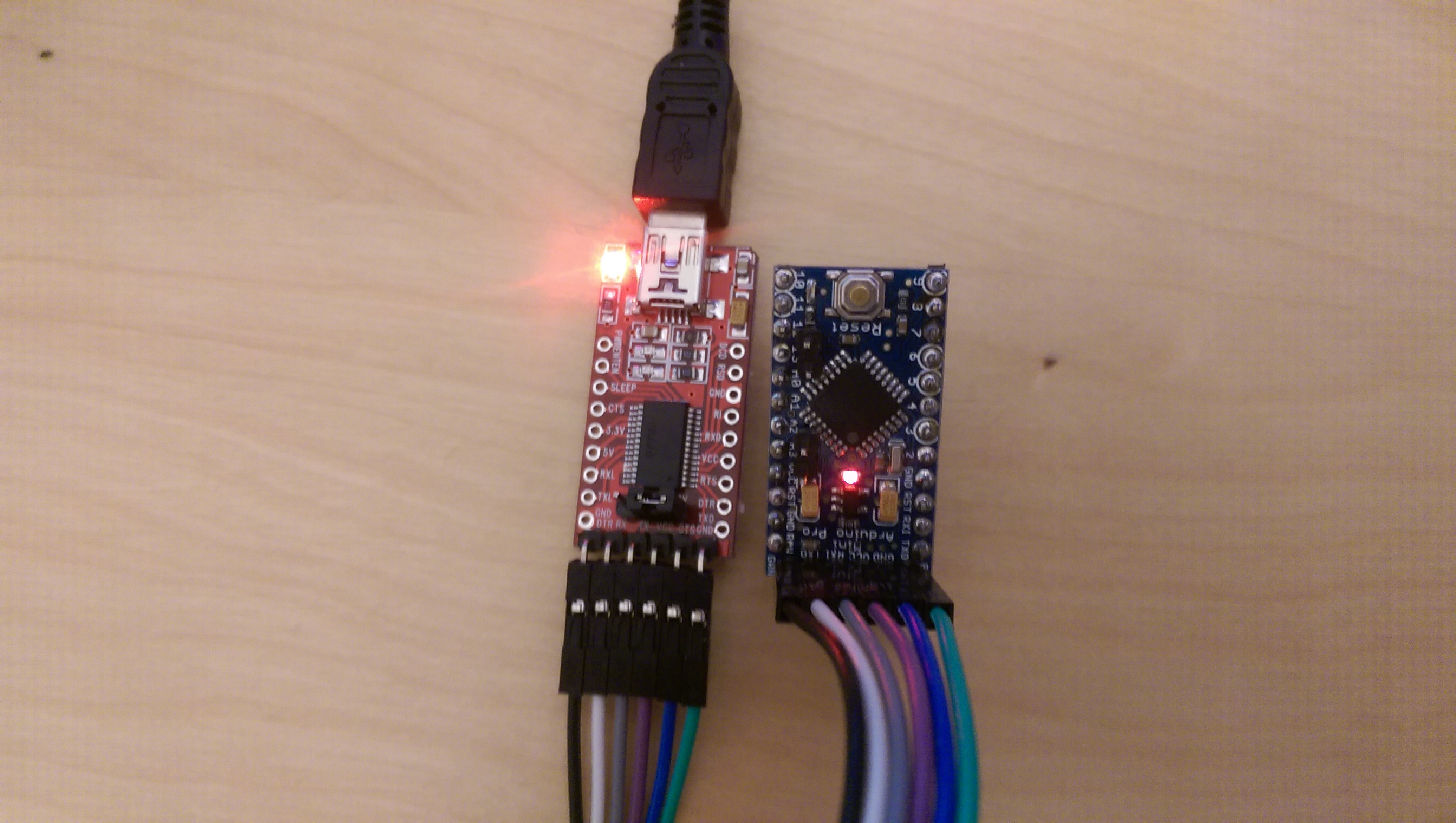
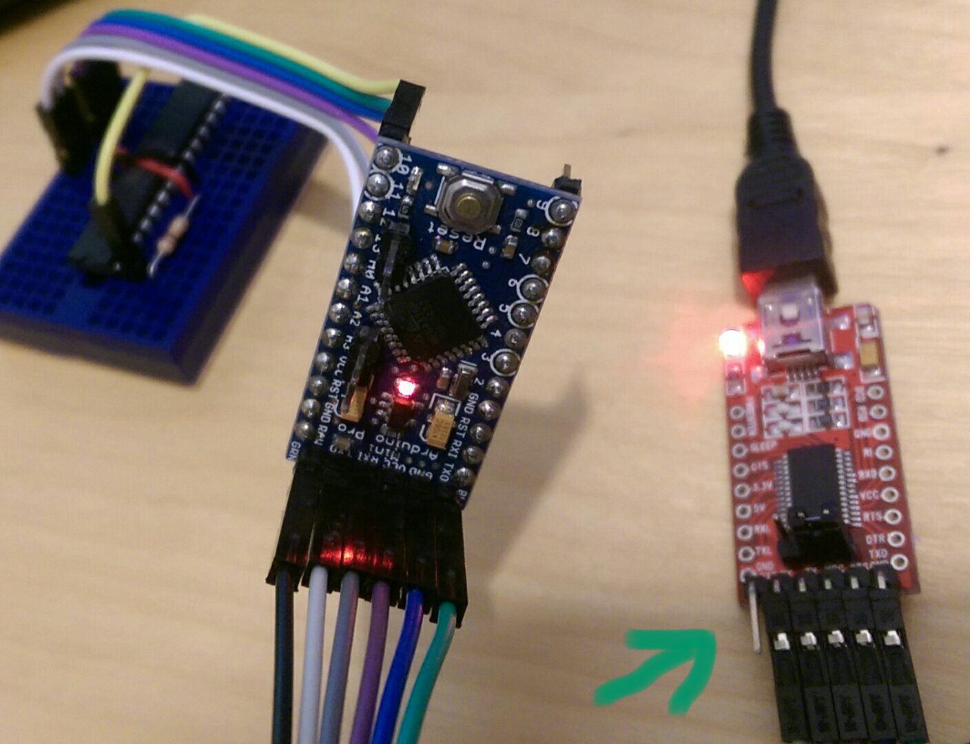
- Program ArduinoISP sketch (from examples) to an Arduino that is to be used as an ISP programmer (I used an Arduino Pro Mini, be sure to select the correct board and Serial Port as normal at this point)
- Disable the reset on serial connect! (In my case I disconnected the DTR line from the USB serial adapter, but you can also use a pull up resistor from Vcc to the Reset pin, whatever is easiest)

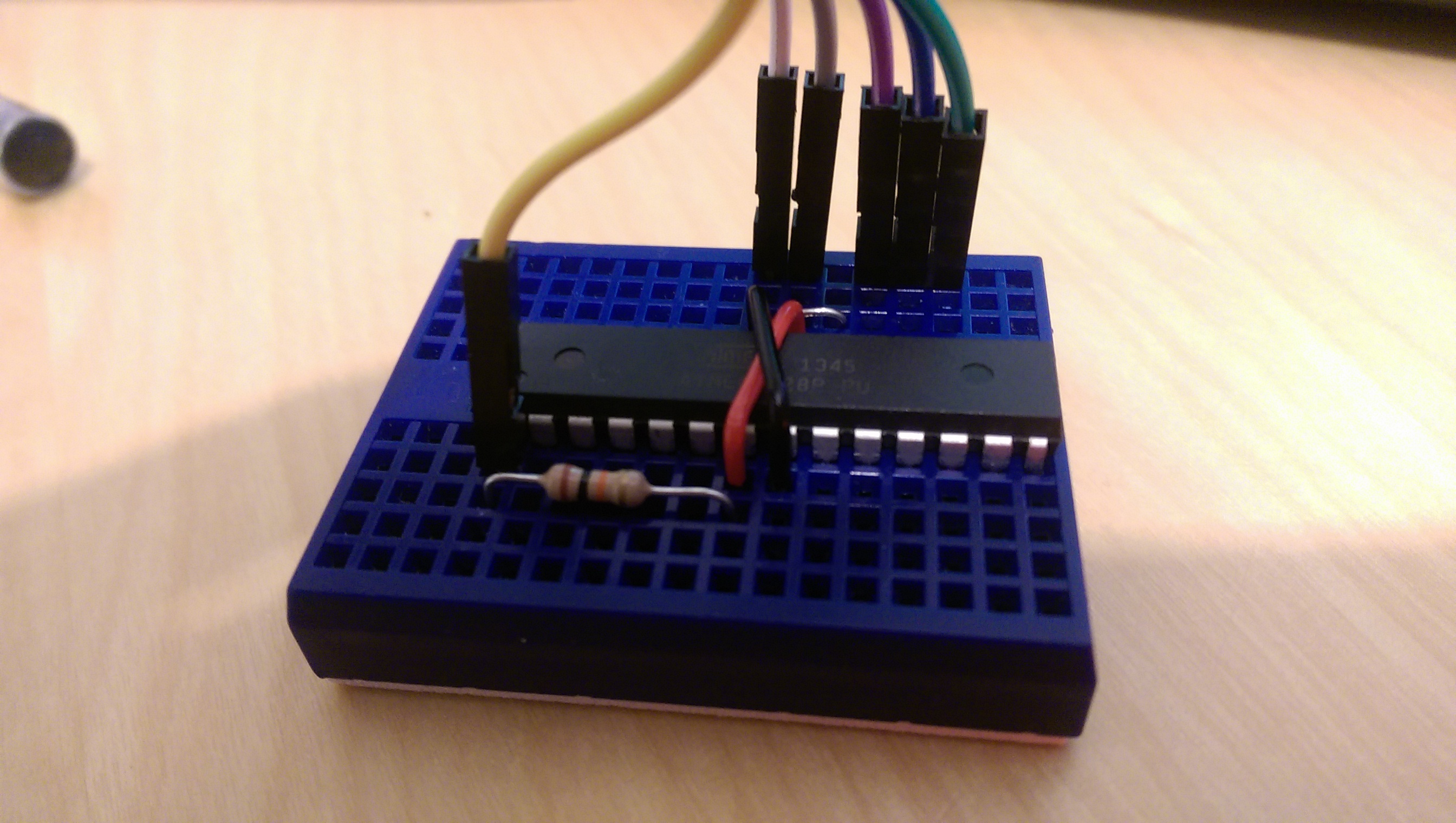
- Wire the Atmel chip to the arduino ISP programmer:
- MOSI (digital 11) to MOSI (pin 17)
- MISO (digital 12) to MISO (pin 18)
- SCK (digital 13) to SCK (pin 19)
- Vcc to Vcc (pins 7, 20 & 21)
- GND to GND (pins 8 & 22)
- Digital 10 to /Reset (pin 1)

- Select your target board settings, the “Arduino as ISP” as the programmer and then select ‘program the bootloader’ from the tools menu.
- Wait a few moments and hopefully there will be a successful status, if so you’re bootloader is programmed.
Using your bootloaded chip
- Wire up a serial port:
- VCC to pins 7, 20 & 21
- GND to pins 8 and 22
- TX to pin 2 (chip RX)
- RX to pin 3 (chip TX)
- DTR to a ceramic 0.1uF connected to pin 1 (enables the automatic reset when uploading the firmware, very useful to avoid having to press a reset button at the correct moment)
- Select a board that has the correct oscillator frequency (and similar voltage ideally) as you are using, then upload a sketch.
Trouble shooting:
Things not going to plan? Start by enabling verbose options in the Arduino environment preferences to see more details and the commands that are being run. You can try and run these on the command line to get more familiar with what each parameter means.
Ensure your bootloader is programmed at the correct speed: If your crystal is a 16Mhz crystal, use a 16Mhz bootloader! I found that my breadboard ‘duino was running at 3.3V but had a 16Mhz crystal on it – that’s not a standard option as it’s too fast for the ‘safe operating frequency’ at that voltage, so selecting the 3v3 bootloader which expects 8Mhz operation caused the bootloader to be unusable as the baud and timeouts were too fast (obvious really!). To get the bootloader working you must program the bootloader with the correct frequency for the clock or the communication won’t work – see the baud rate discussion later, the voltage is secondary, though brown out detection programmed in the fuses may cause problems – for more info on all this, read the datasheet linked above!
The chip must be connected to a valid oscillator according to it’s current fuse settings for programming to work. Other documentation indicates that another internal RC timer is used for clocking the flash writes, so it was a surprise, but I have put it to the test unintentionally and confirmed it.
This is important when you are not using an external oscillator – by accidentally writing fuse settings for an oscillator to a chip that doesn’t have an oscillator, you can’t program it again until an oscillator is connected. You will be able to accidentally change it to require an oscillator as the chip will work on it’s internal oscillator to start with, but once the fuse settings have been updated you can not change them until the oscillator is connected. The oscillator speed shouldn’t matter too much, but it must be there if it is expected.
If you’re struggling, you may want to ensure there is a XTal between pins 9 & 10 with appropriate capacitance between 9 & GND and 10 & GND. (16Mhz Xtal and 22pF most likely).
Hopefully you have managed to get the bootloader on the chip, and the fuse settings will be set as per the board you have selected. You can put your Atmel chip in to your target board and use it as an Arduino communicating over the hardware Serial. Yay!
3. ISP is not just for bootloading!
I wanted to be able to program my arduino through my ‘Arduino as ISP’ set up, and that wouldn’t work. The problem is that, for normal programming, the arduino environment uses 57600 baud, but the ISP we just programmed uses 19200. Simple fix is to change the constant in the ArduinoISP sketch, or so I thought…
It works, but then it stops you programming the bootloader because of the flag passed to avrdude when programming the bootloader that tells it to use 19200.
That can be changed however – by opening the programmers.txt file and creating a new programmer that tells it to program the bootloader at 57600 also.
- open the bootloaders.txt & copy the ‘Arduino as ISP’ entry
- rename all the ArduinoISP.xx variables to MyISP.xx
- set:
myISP.program.speed=57600
Yay, now both boot loader and general programming work through the ISP!
4. How to change the fuses?
I mentioned that the arduino concept of a board controls the fuses (which is what we need to configure differently if we want to use the RC oscillator), so the solution is to create a new entry for a new board in boards.txt. It’s best to copy and paste from a similar board if possible and change the fuses to how you’d like them programmed.
- Copy an existing setting from a similar processor as the one you’re targeting
- Set the fuses by changing the appropriate line(s):
myboard.bootloader.low_fuses=0xFF
myboard.bootloader.high_fuses=0xDA
myboard.bootloader.extended_fuses=0x05
- Now reprogram the bootloader using the ISP method detailed above.
5. How to use the Internal RC oscillator?
If you change the clock speed you must do some other stuff too…
You must use a bootloader that is expecting the given clock speed – to use a 1mhz clock that means making your own booloader variant (easier than it sounds!).
The bootloader source is shipped with the Arduino environment, and a handy make file that specifies the settings for the variants of the bootloader to use. All that needs to be done is modify the make file (copy and paste the definition for an existing variant), change the correct settings, compile (make) the variant and then you’ve got your own variant that will use the correct clock speed for it’s baud calculations and be able to communicate with the host. Yay!
Well, almost… In practice there is another ‘gotcha’. If you are using a slow clock frequency e.g. the 8 mhz clock with the div8 flag to run at 1mhz, then the baud rate generator that down samples the frequency of the clock, requires it to be divided by 16 (or 8 if using the ‘double speed’ option). That all means you end up with a large number of baud rates simply being unusable due to clock drift. Long story short – use 9600 baud for programming these chips as it produces small enough drift that the host and the chip manage to communicate. Others baud rates may work out, but get it working on 9600 baud before trying to get it working faster!
The important changes to the makefile variant parameters are:
myVariant: CFLAGS += -DBAUD_RATE=9600 -DDOUBLE_SPEED
myVariant: AVR_FREQ = 1000000L
myVariant: $(PROGRAM)_myVariant.hex
When you’ve got your variant defined, get a command line in the directory and type:
make myVariant
and it will try.
You may need to define some paths to find the appropriate files – I had to change the following:
CC = /home/will/Downloads/arduino/arduino-1.6.8/hardware/tools/avr/bin/avr-gcc -I/home/will/Downloads/arduino/arduino-1.6.8/hardware/tools/avr/avr/include
Once you have your bootloader, the final piece of the puzzle is to explain it all to the Arduino environment, by modifying the boards.txt:
- tell the compiler what the clock speed is so it gets delays and millis correct when compiling code targeted for your board:
myboard.build.f_cpu= 1000000L
- tell the uploader what baud rate to use (default seems to be 57600)
myboard.upload.speed=9600
- indicate which hex file to program when uploading the bootloader:
myboard.bootloader.file=atmega/ATmegaBOOT_168_myVariant.hex
If you’ve followed all that, then you’ve done well! As a (dubious?) reward , here are the diffs between the original versions (shipped with 1.6.8 Arduino environment) and my working versions of the files. These list every line I’ve added or modified to get a system that works. There are some more advanced features in the file, but I’m sure you can figure it all out!
6. Conclusion:
Now you can run an AtMega328P with one resistor, 3 interconnects at anywhere from 1Mhz from 1.8V to 8Mhz (>~2.5V) and can add an oscillator up to 20Mhz while keeping the familiarity of the Arduino environment.